Microsoft Team Foundation Server (TFS)


Why do we need version controller or source controller? This post will answer this question and introduce a version controller which is introduced by Microsoft (Team Foundation Server) and compare it with the Microsoft visual sourcesafe.

This is a compact post of all above things, most of the things had refer on internet. Thanks every one who write these things on the web.

Let's try to answer above question. Actually why do we need a Version Control System (VCS)? Let's assume you are working on a large project and each single module developed by single programmer and also they need to share their source or builds among each others when they needed. So simply you can suggest a shared folder to hold all the sources and builds which every one can access it. But what's happen when two programmers open same project and edit it by both of them? Exactly it will complicated for both programmers. And also there are no way to control versions ~ can not roll back to previous version. Now you understood the needs of VCS.

You may find available VCS here

Now let's move to TFS.

What is TFS?

Team Foundation is a client-server source control system that uses a .NET Web service to access items stored in a SQL Server database.
  • Version control, for managing source code and other deliverables that require versioning.
  • Work item tracking, for keeping track of such things as defects, requirements, tasks, and scenarios.
  • Project management functions, which allow the shaping of a team project based on a user-specifiable software process, and which enable planning and tracking using Microsoft Excel and Microsoft Project.
  • Team build, for enabling a common process for building executable products.
  • Data collection and reporting, which aid in the assessment of a team project's state, based on information gleaned from Team Foundation Server tools.
  • The Team Project Portal, which provides a central point of communication for a team project packaged as a Microsoft Windows SharePoint Services site.
  • Team Foundation Shared Services, which provide a number of common infrastructure services that invisible to end users but that, are important to tool smiths and extenders.

Ways to access TFS

  • From Visual Studio – through Team Explorer
  • From the command line
  • From the web browser
  • From Microsoft Office products
  • From other platforms or IDEs
  • From Windows Explorer
There are some other products also to access to TFS.

Following figure shows the web interface of the TFS


Comparison between Visual Source Safe and TFS.

Visual source safe is an old software that Microsoft developed for version control. Most of the visual studio programmers are still use SourceSafe. But there is a way to completely migrate from VSS to TFS. We will see that method later. Now let's move to comparison.


VSS
TFS
Description
Security and Project Rights
Low
High

Reliability

Low
High
VSS does not have a server component, while TFS is client server application. TFS writes operations occur in the database by way of stored procedures that are not subject to network connectivity issues.
Scalability
Low
High
TFS can support teams of up to 2000 users whereas VSS is recommended for teams of 20 or less.
Sharing and Pinning
Yes
No
Share or Pin features not in TFS. When you migrate VSS projects to Team Foundation, Pins in a Visual SourceSafe database are replaced by labels.
Check-Out and Check-In
Yes
Yes
In Visual SourceSafe, you must do an explicit check-out and check-in only if you are editing a file. In Team Foundation, every action requires an explicit check-out and check-in.

Team Foundation Features that Do Not Exist in Visual SourceSafe

Visual SourceSafe Features that Do Not Exist in Team Foundation

  • Share
  • Pin
  • Archive and Restore
  • Destroy
  • Keyword expansion
  • Rollback
 Next post will be a complete guidance to migrate VSS database to TFS.


Continue Reading...

Create Window service project in C# - Part 3 (Using Timers in a service)

So now we know how to create, launch and view event log for a Windows service using C#. If you do not have a clear idea please refer following two posts.

 Now let's create a windows service application which use Timers. Because most of the windows services are running to execute specific task periodically. That's mean execute a code after specific time period without user interaction. 

For that purpose you can use Timer component in C# which enables you to execute a code segment periodically. Let's see how this thing worked...

First you have to create a timer object on your service class. I am not going to further describe these things, because you will be able to understand by looking on following code.
using System;
using System.Collections.Generic;
using System.ComponentModel;
using System.Data;
using System.Diagnostics;
using System.Linq;
using System.ServiceProcess;
using System.Text;

namespace MyWinService
{
    public partial class MyService : ServiceBase
    {
        System.Timers.Timer tmrDelay;
        int count;

        public MyService()
        {
            InitializeComponent();

            if (!System.Diagnostics.EventLog.SourceExists("MyLogSrc"))
            {
                System.Diagnostics.EventLog.CreateEventSource("MyLogSrc", "MyLog");
            }

            //set our event log to system created log
            myEventLog.Source = "MyLogSrc";
            myEventLog.Log = "MyLog";

            tmrDelay = new System.Timers.Timer(5000);
            tmrDelay.Elapsed += new System.Timers.ElapsedEventHandler(tmrDelay_Elapsed);
        }

        void tmrDelay_Elapsed(object sender, System.Timers.ElapsedEventArgs e)
        {
            string str = "Timer tick " + count;
            myEventLog.WriteEntry(str);
            count++;
        }

        protected override void OnStart(string[] args)
        {
            myEventLog.WriteEntry("MyService started");
            tmrDelay.Enabled = true;
        }

        protected override void OnStop()
        {
            myEventLog.WriteEntry("MyService stoped");
            tmrDelay.Enabled = false;
        }
    }
}

This code was placed on "Service1.cs" file on my project.

Code explained

 System.Timers.Timer tmrDelay;
 int count;
Declare timer variable for timing purpose and count variable for counting purpose.

 tmrDelay = new System.Timers.Timer(5000);
 tmrDelay.Elapsed += new System.Timers.ElapsedEventHandler(tmrDelay_Elapsed);
Create timerDelay object for 5000ms(5 seconds) delay. Then event handler so that timer will execute the code within the "tmrDelay_Elapsed" method in every five seconds. (Do not worry this event handler code line will automatically generate when you type '+=' and press tab)

 void tmrDelay_Elapsed(object sender, System.Timers.ElapsedEventArgs e)
 {
    string str = "Timer tick " + count;
    myEventLog.WriteEntry(str);
    count++;
 }
This is the event handler for timer elapsed event. When timer elapsed a specific 'interval' time it will execute code within this event handler.

Here adds a new entity on event logger as "Timer tick 1" , 2, 3, 4 ....

Other codes are as it is on previous post. Therefore I am not going to explain those here.


Now build and install your solution as describe in Part 1. Then you will see some thing similar to this in "Event Viewer" or "Visual Studio".


As you can see when each time timer elapsed it will add new entity to logger. So now it's your turn place any code in timer elapsed event to execute it periodically.

Complete project can be downloaded from here.
Continue Reading...

Create Window service project in C# - Part 2 (View event logs)

This article series describes about creation of windows service application using C#.net. My previous post describe about the creation and installing of the windows service using C#. This article will introduce you to the way to check logs on windows system.

Can you can remember, we create an event log for our windows service project. But where should I look for these logs to view those. This article will answer for that question.

You can check whether our new windows service is installed or not from Computer management and also you can start you service from here by clicking on "start". As we write on our program there is a action when starting the service to write "MyService started" on event log. (in OnStart method)

You can check these logs using either Visual studio or event viewer on windows.

Visual studio

Just open Server Explorer from visual studio to view all services. If you unable to find the server explorer, you can select it from view menu. (Or press Ctrl+W then L in VS 2010). You will find your event log under Servers --> [Your PC name] --> Event logs. When you expand your event log you will see all the logs which are loged by your service. (nor Refresh the list)


Event Viewer
Just open "Event viewer" from start menu and you will find your event log and its details. Also you can clear your logs from here.


Continue Reading...

Create Window service project in C# - Part 1 (Create and launch)

Windows service is a running executable on windows which perform a specific functions without user interaction. So you can even create a windows service to do a specific function without your interaction. There is an easy way to create a windows service application in C#. This article describe step by step of creating windows service application in C#.net. and my next parts will describe further more about...

Step 1
Open visual studio and File--> New --> Project. then select "Windows service" and type name and location of your project.


Step 2
Then go to "Service1.cs" file's design view. Then Properties of Service1 and change the 'Name' and 'Service name' as you wish. I changed those as "MyService" as you can see on following screenshot. Then click "Add Installer" to add an installer for this service.

Step 3
Then click on 'serviceInstaller1' component on 'ProjectInstaller.cs' file's design view then get its properties. Now you can change the properties of serviceInstaller1 as shown in following figure.

Make sure the Service name is equal to the service name that you enter for Service1.cs's properties and select StartType as Automatic. Then let's see properties for serviceProcessInstaller1 on ProjectInstaller.cs. You should change the Account as LocalSystem. It will prevent asking username and passward from the user when install this windows service.

Step 4
Now let's see how to get notified whether our service is running or not. For that you can use EventLog component as describe as followings. First go to Service1's design view and the add a eventlog component from tool box.


I changed added event log's name as 'myEventLog'. So then move to the coding... (switch to the code view of Service1.cs file)
Add following code segment to immediately following to the initialize component method calling on the constructor of the MyService class.

 if (!System.Diagnostics.EventLog.SourceExists("MyLogSrc"))
 {
    System.Diagnostics.EventLog.CreateEventSource("MyLogSrc", "MyLog");
 }

 //set our event log to system created log
 myEventLog.Source = "MyLogSrc";
 myEventLog.Log = "MyLog";


This will create a system event log and bind our event log to created log.
Then add following code segment to the override method of OnStart. There are more override methods which are on ServiceBase class as our class extends the ServiceBase class. You can try those methods also for further more actions.

 myEventLog.WriteEntry("MyService started");


OnStart override method can be use to execute actions when our service starts. Because OnStart method executes when a Start command is sent to the service by the Service Control Manager (SCM) or when the operating system starts (for a service that starts automatically).

Let's try OnStop method also. So enter following code segment in OnStop method.

 myEventLog.WriteEntry("MyService stoped");


Now your code should like this,


Now our event logger part finished. You can build this project by pressing F6. (If you try to run this project you will receive an error message which notify you "cannot run or debug... first install this service.." like that) So let's move to install our service on windows.

Step 4
To install the service first create an installation project for our project. Let's create it...
Right click on your solution (not project) from solution explorer window and point to the Add then click on New Project...


Then select Setup Project from the list which can be found under Setup and Deployment category. Then type name for your project then Ok.


Now you can see the new project on solution explorer, right click on it and point to Add then click on Project Output... . Then select your project name and select Primary Output.


Then again right click on setup project and point to View then click on Custom Actions. You will see the custom action window. Then right click on Custom Actions then Add Custom Action . You will see the Select Items from Project window. Select Application folder from the Lock in combo box and select Primary output from (active) then Ok.


No you can see, it will add Primary output for all four actions (Install, Commit, Rollback, and Uninstall).


Now we are ready to install our new windows service on windows. Just right click on setup project and select Install from the drop down menu. Now you will see the installation wizard just like normal installation.

That's all for creating basic Windows and installing windows application in C#.net. You can see your service on windows service list. Just go to Computer management by selecting it from start menu. And navigate to Services which can be find under  Services and application category.


Complete Visual studio C# project can be download from here.

My next post will describe how to check your event log to ensure your program.
Continue Reading...

Opencv 2.4.1 instalation libpng error

Now I am hardly working on my research project, It uses Opencv for image processing. Then I heard about opencv latest version released (2.4.1). This post is about an error that I got when I was going to install Opencv 2.4.1. This post does not explaining all about Opencv installation. If you need complete installation guide, just google it.

The error that I got when compiling the Opencv source is,

Linking CXX shared library ../../lib/libopencv_highgui.so
/usr/bin/ld: /usr/local/lib/libpng.a(
pngget.o): relocation R_X86_64_32 against `.rodata' can not be used when making a shared object; recompile with -fPIC
/usr/local/lib/libpng.a: could not read symbols: Bad value
collect2: ld returned 1 exit status
make[2]: *** [lib/libopencv_highgui.so.2.4.
1] Error 1
make[1]: *** [modules/highgui/CMakeFiles/
opencv_highgui.dir/all] Error 2
make: *** [all] Error 2

When I got this error I search on google but I could not find any solution for that. Here is the solution that I suggest and it succeed  for me.

According to my point of view this can be occurred version mismatch between Opencv's libpng and libpng installed on your system. But there is a libpng already included in opencv source download. So you can use that libpng to compile opencv source.

Solution
The error saying about libpng package therefore if you get this error too, you should set a flag BUIL_PNG = on when configure the cmake make file generation process. This allow opencv to compile its source using libpng source that include in the opencv source directory. I used cmake GUI to generate make file on Ubuntu. Here you can easily set that flag on as you can see on following figure.


That's it now you can compile opencv without this error.
So happy opencv coding!

Continue Reading...

Make new Proteus device with its PCB package. (Here for 7 segment display))

I am here after long long long time. Therefore I thought post a valuable thing which I have done with proteus. That is making a new device for proteus. One day I had needed to design a PCB which including seven segment displays. But I couldn't find any Proteus PCB package which is match with 15.24mm seven-segment display pin-out. Therefore I encouraged to create a PCB package for a seven segment display. So following steps will describe to create a new PCB package which totally match with your particular hardware device.

Steps to create PCB package for seven segment display

Step 1- Import a seven segment display to Proteus device list from existing devices to modify it. For that simply go to Library->Pick device/Symbol... (or press P) and then type 7SEG-COM-CAT then it will provide all the available Common Cathode 7 segments with different colors. Choose a one of the device then press ok.

Step 2- Then draw the imported seven segment to the sheet. Now we can modify the device in order to meet our actual hardware device's requirements (pin numbers, common pins,etc...). Then right click on it and select Decompose to modify it

Step 3- This seven segment display has only 8 pins but in actual 7 segment display has 10 pins which are 7 input pins, 2 common cathode pins, and dot input pin (DP). Therefore first we need to modify this device to make additional 2 pins. So you can just add another 2 pins from the tool bar to the device. The tool to add pins and the modified 7 segment display are,


Now you have carried out the requirement for number of pins of the device.

Step 4- But still we do not assign the actual pin numbers for the device. This will need to define PCB package for this device. Now double click on a pin to define the pin number. It will display a widow which asking the pin name and number. Type the pin numbers for the particular pin name (A-7, B-6,...) as describe in following figure. (Do not care about other options in the window.)

But there is an exception... What should be the names for pins those we have drawn on the sheet? so you can put any name for DP pin BUT you should put the name for our second common cathode pin as the name of the pin which already exists as a common cathode. (Because they are common pis) For my Proteus it is COM, so I put COM for name of the second common cathode pin.


Now configurations for this device is completed at here.

Step 5- Now start Proteus ARES to make our PCB package for this device. Here we do not have a package as just like in previous situation to modify it. So we have to make our own package from the beginning. Therefore you will need the distances between pins and other dimensions to draw the PCB package of your device. So you can download the data sheet of your 7 segment display to obtain the dimensions. My 7 segment is 15.24mm one and its dimensions are,


Step 6- First of all press M to change the scale to mili meters (It will display on the right bottom of the ARES window and you can use several grid scales from View->Snap 0.1mm , Snap 0.5mm , etc..) Draw the pin holes using Square or Circle pad mode. Also you can use Dimension mode to measure the distance from one place to another. Carefully draw the diagram with correct measurements. Then assign pin numbers by double clicking on a pin.


Then you can use other 2D graphics to make your package nice.


This number (8) , square and dot are 2D graphics only but it will make beautiful when you view this as a 3D view.

Step 6- Then select all drawn component and Right click and select Make package. Then fill the text boxes with particular data. You can use any name for your package name and other things (These are only depend on categorizing your component in the Proteus library). Then press Ok to make the package.


Now we have our own PCB package for 7-segment display. So now we can make our 7-segment device which is modified earlier in Proteus isis.

Step 7- Then go back to our ISIS design window and make a device by selecting all drawn components, right click and select 'Make device' from popup menu. Now you can see following window. Before that it will show you a warning message Just click ok to ignore that.


Type any unique name on the Device name field and Type a letter on 'Reference Prefix'. This is the letter you can see when draw a new device of your device such as D1, D2, D3.... Then click next.

Then it will show a black window with a text as "ARES PCB libraries are not installed or the specified package cannot be found in any library". So to add our already created PCB package to this device click on "Add/Edit" button.

Then click on Add button to add a PCB package. After that it will show a window named "Pick package" then type the name you have given in the Proteus ARES as the 'Keyword' and select that package. Now Proteus load your package for you and show it in the black area of the window as follows.

Now click on 'Assign package(s)' button to add this package to this device. Now you can see the PCB footprint on the black area which show a message(ARES PCB libraries are not installed or the... ) earlier. Then click next, next... and Ok to finish the wizard. and now you have a 7-segment display with your own PCB package.

Step 8- Choose this device from pick device window and place it on the sheet and you can create a PCB also using this device. This is the solution for our problem here. So enjoy it.........

This is a PCB which I created using above method (ISIS schematic design and PCB design)

Continue Reading...

Revert Ubuntu boot loader after installing Window 7

This post will describe to install Ubuntu GRUB boot loader after installing windows 7 on a PC that already Ubuntu installed. Also this is a problem that I faced after installing Windows 7. Suddenly my Windows 7 installation was crashed and I formatted Windows installed drive and reinstall the Windows 7. I was used Windows and Ubuntu installed on different drives as a dual boot. But after installing windows 7 Ubuntu boot loader was overwritten by windows boot loader and that boot loader does not list my Ubuntu installation. Therefore I could not select Ubuntu to load and windows boot loader automatically boot the Windows7 itself. To overcome this problem we have to overwrite GRUB boot loader on windows boot loader. Follow the steps that I explained bellow correctly to do that.

This method will copy boot settings from Ubuntu Live-CD in order to boot from GRUB boot loader.

Step1- Insert Ubuntu Live CD into CD drive and boot from it.


Step2- Click on 'Try Ubuntu' (on Ubuntu 11.04) to load Ubuntu from Live CD without affecting to your computer.


Step3- When Ubuntu Live desktop appear Run 'Terminal' (Application-->Accessories-->Terminal) to execute following commands.
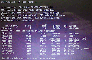
Step4- In terminal type sudo fdisk -l
It will display all partitions on the hard disk with some details
Identify the partition which Ubuntu installed by checking 'System' column from the above result. The partition which has 'Linux' under system column is the partition of Ubuntu installed.

But here(in my computer) 3 partitions hold 'Linux' under system column. Therefore you should identify the correct partition. For that you can use 'Disk utility' software(it is already included in Live-CD session). Still complicated to identify the partition please be patient, it can be identify in next step.


Step5- Mount the Ubuntu partition drive
    sudo mount /dev/sdXX /mnt
    (Example- sudo mount /dev/sda9 /mnt)

Now go to Home directory(Place-->Home), go to root directory and go to mnt directory by double clicking. Make sure here the folders such as 'boot', 'opt', 'usr' and 'bin' etc exists on this directory(/mnt directory). If not you could not mount Ubuntu installed partition to the mnt, so unmount it and mount the correct partition to the mnt.(To unmount type sudo unmount /mnt)

Step6- If you have different partitions for boot, home, etc... mount them to each corresponding directory in /mnt directory.
Example- sudo mount /dev/sda3 /mnt/boot
                sudo mount /dev/sda10 /mnt/home
(to check whether you mount correct partition to the correct directory check out the content of each directories)

Step7- Now all the files that are required had mounted and ready to install GRUB boot loader.

sudo grub-install --root-directory=/mnt /dev/sda

(Note-That's /dev/sda the hard disk itself, not Ubuntu installed partition)
If it says grub-install is not a command then you had some mistake on mounting.

Step8- Unmount and restart
    unmount all the partitions that mounted.
    Restart the computer - sudo reboot


That's it. Now you can see the GRUB boot loader with all the installed operating system listed.
Continue Reading...

Use Android phone as a modem (Internet connection to PC through Android phone)

First of all I would like to say happy new year to all of you. So this is my first post in 2012.

This post is based on a problem that I faced after -->brought an Android phone. Oh I forgot to say you, I brought an Android phone it is Sony Ericsson Experia X10 mini pro. The problem that I faced is 'How to connect this phone and establish a internet connection in PC'. You know most of the normal phone that capable GPRS can connect to PC(USB or bluetooth) and establish the internet connection over phone. Earlier I used a Nokia phone(Nokia 3120 classic). It can be used as a modem to pc, therefore I could brows internet in PC through the phone.
But in this Android phone it is a little bit different. Because this is an Android phone *#%@.=+.

Simply here are steps to configure your Android phone as a modem.

First of all you have to download and install software needed in both sides, phone and PC. This task is just like a client-server application. So first, lets install on the phone.

The software is EasyTether. EasyTether allows you to shares your phone Internet connection with computer/laptop/notebook (Windows 7/Vista/XP 64-bit/32-bit, Mac OS X 10.4/10.5/10.6/10.7, Ubuntu 10.4+, Fedora 13+)

you can download Easy Tether from Android market and install it from your phone it self. But there is a thing to say you this is not a Free software. But Lite version of Easy Tether is available in Android market but the latest version of the EasyTether Lite has some restrictions since it is lite version. Such as blocking secure HTTP sites....... Therefore this is not a complete solution. But there is a way to Activate the EasyTether. Follow these steps to achieve the EasyTether.

The older version of the EasyTether has the Activation code for full version. Therefore you have to install an older version of Easy tether to get the code.

  • First download EasyTether 0.9.3 apk file from here or here.
  • Install the apk file manually to the phone.
  • Open the EasyTether from the phone ans just go to 'About' page and write down 5 digit code (under 'Registration code'). So this is the activation code for your phone.
  • Now uninstall EasyTether 0.9.3 from your phone to install latest version.
  • Install latest version of the EasyTether Lite version(free version)from the Android market.
  • Open it. In first start, EasyTether will show a dialog box about a setup wizard or some thing like that. Just cancel it(You can get it later from setup) and tap on 'Activate EasyTether' to activate the product.
  • Here you should type the 5 digit number which you written under 'Activation code'
  • Now you have the full version of the EasyTather with all capabilities.

Now tap on 'Setup/Settings' and tap on 'USB Tethering setup' to configure your computer for EasyTether. now a setup wizard for the configuration will open and you can easily follow the instruction. This setup wizard is more descriptive and easy. Therefore I think that is no need to explain these steps here. Additionally you have to download the EasyTether software for PC.(The setup wizard will inform you to download and install it to your PC).

Additionally make sure the network drivers installed on your PC. In Windows you can be found it in 'Device manager' under 'Network adapters' named 'Easy Tether Network Adapter'.

Finally you will be able to connect to internet through your Android phone.

To establish the connection just plug USB cable and click on 'Connect' by right click on the EasyTether icon from sys tray in Windows.


Continue Reading...